Emergency Door Release Explained: Ensuring Safe Exits in the UK
Published by STR UK Distribution on 5th Feb 2026

Emergency Door Release (EDR) units are safety devices used in access-controlled doors to ensure a door can be released quickly in an emergency. They are most commonly used on escape routes where electric locking (especially maglocks) is fitted. This guide explains what an EDR does, how the contacts work, and the most common wiring principles.
What Is an Emergency Door Release (EDR)?
An Emergency Door Release (EDR) is a manual release device that removes power (or changes a control signal) so an electronically locked door can be opened during an emergency. Many EDRs are “break-glass” style (or resettable equivalents) and are positioned near the controlled door on the escape route.
How EDRs Work in Access Control Systems
- Manual release function: Activating the EDR changes its contacts so the locking circuit is interrupted and the door releases.
- Fail-safe behaviour: Maglocks are typically fail-safe (power on = locked). Removing power releases the door.
- System integration: Depending on the design, the EDR may also provide an auxiliary signal to another device (e.g. an input on a controller or interface).
Single, Double and Triple Pole EDRs
EDRs are commonly described by their pole count (how many separate circuits they can switch):
- Single Pole (SP): switches one circuit (one line).
- Double Pole (DP): switches two circuits (often both +V and 0V to a maglock).
- Triple Pole (TP): switches three circuits (often two for lock power plus one auxiliary signal circuit).
For maglocks, a double pole approach (interrupting both supply lines) is widely considered best practice because it fully isolates the lock circuit when the EDR is activated.
Why EDR Specification Matters
On escape routes, the release method must be reliable and predictable under emergency conditions. Correct specification and wiring helps ensure:
- the lock fully releases when the EDR is activated,
- the circuit is not left partially energised,
- any required auxiliary signalling operates correctly (where used).
Wiring Diagrams: Typical EDR Contact Behaviour
The diagrams below show typical wiring principles for EDR contacts. These are illustrative examples to help explain contact behaviour and common configurations.
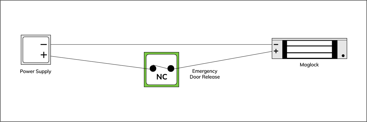
Single Pole – Normally Closed (NC)
What it does: In the idle state, the contact is closed and power flows to the maglock. When the EDR is activated, the contact opens and power is removed.
Single Pole – Normally Open (NO)
What it does: In the idle state, the contact is open so power is not supplied through that contact path. This is shown for reference to illustrate NO behaviour and is generally not used as the primary release method for fail-safe maglocks on escape routes.

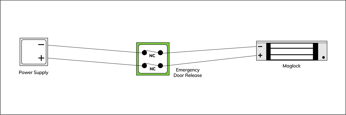
Double Pole – Normally Closed (NC) (Recommended for Maglocks)
What it does: Both supply lines to the maglock pass through NC contacts. When the EDR is activated, both lines open, fully isolating the maglock and ensuring a clean, reliable release.
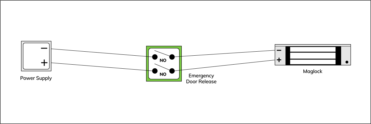
Double Pole – Normally Open (NO)
What it does: Shown for reference to illustrate NO behaviour on a double pole device. In typical maglock release designs, NC contacts are used to interrupt power when activated.
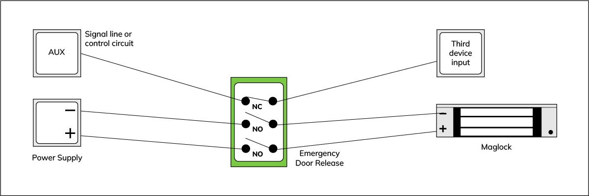
Triple Pole – Two Power Poles + One Auxiliary Circuit
What it does: Two poles are used to interrupt power to the maglock (commonly NC), while the third pole can be used to switch an auxiliary circuit (for example, signalling an input on another device). This is useful when a system requires a separate “EDR activated” signal.
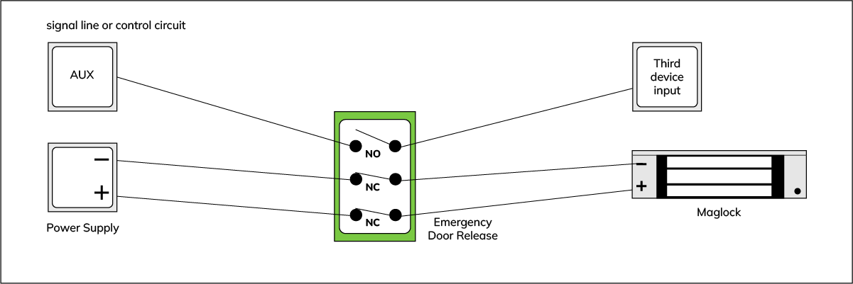
Triple Pole – Auxiliary Trigger (Normally Open)
What it does: In this example, the auxiliary circuit uses a normally open contact that closes when the EDR is activated, allowing a separate device input to be triggered at the same time the maglock power is interrupted.
Single Throw vs Double Throw (ST vs DT)
“Throw” describes how many output paths a contact can switch between:
- Single Throw (ST): one input connects to one output path (open or closed). Common examples include SPST or DPST devices.
- Double Throw (DT): one input can switch between two outputs (NC when idle and NO when activated). Common examples include SPDT or DPDT devices.
Real-World Example: DPDT Contacts in EDR Wiring
If an EDR provides COM, NC and NO on each contact block, it can be used to both:
- interrupt power to a maglock using the NC path, and
- trigger a separate input using the NO path.
Whether you use NC or NO depends on the function required. For fail-safe maglock release, the most common approach is using NC contacts to interrupt power on activation.
Summary
- EDRs provide a manual release method for electronically locked doors, supporting safe exit during an emergency.
- For maglocks, a double pole NC approach is commonly preferred to fully isolate the lock circuit when activated.
- Triple pole devices can add auxiliary signalling alongside lock power interruption where required by the wider system design.